Objective:
The goal of this project was to measure the angle of inclination of a bicycle while it is being ridden. In some cases a single accelerometer would suffice to determine the angle of the hill – When velocity is constant or zero. But for all practical purposes, when a biker wishes to gauge the slope of a hill being climbed, the bike is constantly accelerating and jerking back and forth with pedaling motion. The rider might also be experiencing a constant, more gradual acceleration or deceleration up or down the hill. In these cases the accelerometer readings would be skewed by the linear acceleration of the bicyclist.
One way to accommodate for skewed accelerometer readings is to directly measure this linear acceleration and subtract it from the accelerometer reading. This was the approach that our team took. Implementing this approach was relatively straightforward; an encoder was attached to the rear wheel and an accelerometer was mounted to the frame. We were able to derive a relatively stable acceleration value from the measured position of the wheel and by factoring it into the angle calculation, we saw relatively accurate results even before implementing data smoothing. Our team used the following equation to give the corrected (un-skewed) hill angle:
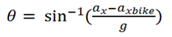
In the preceding equation axbike is the derived linear acceleration and ax is the accelerometer’s x component reading. Because this equation looks only at one component of acceleration, accelerometer sensitivity is a consideration. Our team continued with this approach as we determined that in normal conditions, a cyclist would not tilt to the range of angles corresponding to a low accelerometer sensitivity.
Block Diagram:

Electronics
Encoder:
Our team used the CUI AMT 10 Capacitive Modular Quadrature Encoder to measure wheel position. This encoder is a capacitive encoder which utilizes a PCB rotor with a sinusoidal metal trace that modulates a transmitted electrical field. The modulated signal is then passed back to the transmitter where it is compared against the original and a calculation is implemented. Because of this method of operation, the theoretical resolution can be arbitrarily high and can also be adjustable. This encoder worked well for our team as it provided a level of resolution which allowed for an accurate value for linear acceleration to be derived. As this encoder has a selectable resolution, we chose the highest value of 2048 pulses per revolution (PPR) which corresponded to a value of 8192 counts per revolution after quadrature decoding. This corresponded to a sub-millimeter linear resolution of the bicycle which was smaller than the allowance in the mechanical linkage.
Accelerometer:
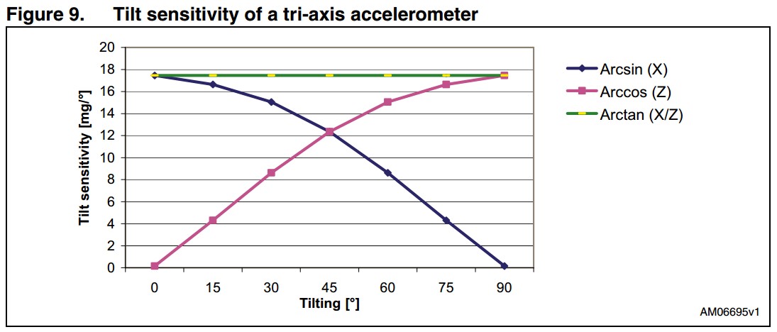
Our team used the ADXL362 3-axis MEMS accelerometer. The x-direction (Direction in which the bike travels) acceleration component of the 3-axis accelerometer is used to gather acceleration data that represents the sum of the angle and linear acceleration vectors. The accelerometer interfaces with the NU32 through SPI. As discussed previously, the sensitivity of the accelerometer to metering a change in orientation depends on the change in vector magnitude of a given component. When a vector is reading close to g, an incremental change in angle will not change the value read by the accelerometer very greatly. When the vector is close to zero, the same incremental change will readily display a much greater change in the size of the acceleration vector. We determined that a cyclist will not leave the region of reasonably high tilt sensitivity of the arcsin function (below 45 degrees) and as such we utilized it in our implementation. Fig. 2 shows the graph of accelerometer tilt sensitivity vs angle.
LCD:
A 16 x 2 LCD screen and a Hitachi HD44780 LCD controller was used to display the bike’s inclination and velocity.
TFT:
A TFT screen (ILI9341) was used to display both the bike’s inclination and the angle of the handlebars as a function of time. It has an additional feature where it would measure the handle bar steering angle. The TFT screen communicates to the NU32 using SPI. The TFT is used on a breakout provided by Adafruit. The library and source files were written from scratch in order to interface properly with the NU32, some of the initialization of the registers code were taken from the github repository of the Adafruit.

Potentiometer:
The potentiometer was mounted such that the wiper moved with the handlebars. The voltage value was converted to a digital value which was then scaled and converted to an angle that shows the angle of steering.
NU32:
NU32 is a PIC microcontroller breakout board developed at Northwestern University. The NU32 is used for to connect all sensors and displays. A 6v battery that powers the NU32 allows our entire setup to run independently from a wall outlet or computer.
Mechanical Design
An important factor in our design approach was the choice to design for robustness and rideability right from the start of the evolution of the bike inclinometer. Our team attempted to identify potential sources of error which could be introduced by physical interfaces in the final product and take steps to decrease this error as much as possible. We decided that a robust linkage with as little allowance as possible between the bicycle’s back wheel and our encoder would be integral to receiving accurate information about the bike’s linear acceleration. Our solution involved taking advantage of the bicycle’s flip-flop hub on the rear wheel to build this solid linkage. We selected a chain and sprocket encoder drive to connect these two components as it did so in a way that was both robust and accurate. The sprocket which ended up on the encoder shaft was from a previous project which explains the 4:7 gear reduction, a factor which was accounted for in the conversion from encoder counts to linear distance. This gear ratio, the encoder resolution, and the bike wheel’s circumference comprise the expression relating encoder position and the bike’s linear position.

A potentiometer was attached to the lower portion of the handlebars and fit into the frame. The accelerometer, NU32, TFT Screen, and LCD screen were all placed next to each other on top of the frame on top of a specialized mounting platform. These components were attached right next to each other because of the difficulties associated with SPI communication over long wires.

It was important that the mount which supported the PCB platform and secured it to the bike frame was rigid. This was an important step towards getting low noise readings from the accelerometer. The mount basically operated like a clamp so that it applied a force to both the top and bottom members of the bike frame. This force was applied by a hex screw which was adjustable allowing for the mount to easily be positioned. The mount was designed to provide a good location for the PCB platform which would allow the cyclist to easily read the output data from the two displays.

As shown in Figure above, the PCB platform sits atop the mount. We used an adhesive to set 4 stand-offs onto the PCB which were tapped for easy connection to the PCB platform. The platform provided a nice foundation for mounting our electronic components and also provided a good location for the mounting of our battery pack.
PCB Design:
The PCB schematic was created using eagle. The board and schematic were designed to be used with the NU32

Results:
Acceleration test on flat surface:
The Bicycle Inclinometer throws at most 2 degrees of error when tested with a controlled acceleration on a flat surface. When subjecting the bicycle and bicycle inclinometer to the same acceleration while still on a flat surface but without the linear acceleration factor (back wheel locked), the error increased by a factor of 10. This can be seen in the following still from the video in Figure 9. Some factors which increased accuracy were: Synchronous polling of the accelerometer and encoder and the application of a simple moving average to both data streams. Data was collected and displayed at a rate of 8Hz.
Stationary Angle test:
Our inclinometer was accurate to about half a degree when tested on a flat surface and measured against a protractor. The test was done for angles less than 45 degrees from level. This value seems to be an acceptable level of error for a cyclist attempting to meter their angle of inclination on a road.
Counter-Steer Experiment:
The TFT screen also displayed the bike’s handlebar angle. The purpose of this was to measure if cyclists usually counter-steer before entering a corner. From the data collected in test runs we were able to conclude that while there is a bit of counter-steer which a cyclist invokes before entering a turn, cyclists of average skill level will correctively steer very often while traveling at a low to medium speed. This is shown in the data which is not as smooth as one would predict due to the multitude of fine adjustments being made to the handlebar to accurately prepare for a turn. This can be seen in the video.
